Ciro-flex TLR Camera Repair/ restoration
The Ciro-flex is an American made TLR manufactured during the 1940s and ’50s. The Ciro camera company was purchased by Graflex and the Ciro-flex continued to be manufactured as the Graflex 22. Altogether, there were six different Ciro-flex models, A through F. The model A has a slightly different focusing mechanism, and is not quite as common. The B and C models have a non-synchronized shutter while the D, E, and F models have flash synchronization. The B and D models use the simple Alphax shutter while the C, E, and F models use the high-quality Rapax shutter. Early versions of these cameras have a parallax correction frame under the ground glass. In later models, the frame was replaced with a fresnel lens in order to help brighten the focussing screen. Overall, these are no-frills cameras with only a simple knob winder, no double exposure prevention or automatic film counter. However, they are sturdy cameras with good lenses and shutters. The model F has an excellent four-element lens that is quite sharp. All of these cameras are capable of taking very nice pictures and are still very usable for low-budget medium format photography.
Unfortunately, you will almost always find these cameras in terrible condition. The lenses, reflex mirror and ground glass are usually hazy and the shutter sticky or inoperative. In addition, the steel body will rust anywhere the paint has chipped off, and, often these cameras look like they are well beyond repair. However, as long as the lens isn’t damaged from fungus, a Ciro-flex can almost always be brought back to life. The rust on the body doesn’t really affect the performance of the camera; it just looks bad. These are easy cameras to work on and make an excellent first project if you are interested in learing how to repair a TLR. In addition, these cameras can be bought for very little money (often $20-30) and so if you are willing to put in a little work, you can have a nice medium-format camera for a very low price.
In this article, I show disassembly of the focus mechanism. Usually, this isn’t necessary. The focus cam can be cleaned using cotton swabs dampened with cigartte lighter fluid by reaching in from the back of the camera. On this camera, there was some dried out grease and I needed to soak the parts in solvent to get everything clean. As you can see, there isn’t much else to disassemble on the Ciro-flex.
A very good book on the Ciro-flex camera, and TLR usage in general, is PHOTOGRAPHY with the Ciro-flex by Bruce Downes. I have uploaded a 300dpi scan of the information in a Ciro-flex brochure.This describes the features of models B through F and shows the original prices.
 |
To clean the focusing screen and/or reflex mirror, remove the four screws around the top cover and lift the cover off.
NOTE: on early versions of the Ciro-flex, with the parallax correction frame, you will not be able to lift the viewing hood off until the frame’s connecting lever is disconnected. In order to disconnect the lever, you need to remove the front panel, rotate the focus to the shortest distance and then remove the screw located on the right side of the lens standard. |
 |
The focusing screen and fresnel lens are held in place by two spring clips. Turn the hood over and remove the two clips. You will need to then slightly spread the frame to allow the screen and lens to fall out.
There are also four tabs on the frame that may be bent inward slightly to help hold everything in place. On cameras with the parallax frame, these tabs hold the frame together. Bend the tabs straight to allow the frame to separate. |
 |
With the hood off, you can reach the rear element of the viewing lens for cleaning. However, these lenses seem to get a coating of haze on the inner surfaces, and may need to be disassembled to get them clean. In addition, if you need to disassemble the focus, you will need to remove this lens in order to get the front panel off.
To remove the viewing lens, loosen the retaining ring at the base of the lens, then unscrew the lens assembly from the body. This ring is often tight. You can use a soft-jaw plier to remove it. It is easier to remove this lens after the shutter is removed from the camera. If you are going to remove the shutter, wait until the shutter has been removed before removing the viewing lens. The outer lens elements are held in place by screw-in retaining rings that have no slots for a spanner. Use a rubber furniture leg cup to unscrew the rings. These rings may be stuck from oxidation. A small amount of solvent, such as alcohol or laquer thinner, will help loosen the rings. To adjust the focus on the viewing lens, just loosen the retaining ring and rotate the lens until the image on the focusing screen matches the taking lens focus. Retighten the retaining ring when done. |
 |
The shutter is held in place by a retaining ring accessible through the back. On models without a flash connector, just unscrew the retaining ring and the shutter will lift out.
On models with flash, you need to disconnect the flash wiring before removing the shutter. Open the back and unsolder the flash connector you find there. There is another flash wire under the front panel that will need to be unsoldered as well. Remove the front panel to gain access to the second wire. |
 |
To remove the front panel, first peel off the leatherette from the front. The leatherette is made of paper and you should not use any liquid to try and loosen the glue. It is quite common for the leatherette to disintegrate when you try to remove it, so take that into consideration before deciding the remove the front panel. Remove the four screws and the front panel can then be lifted off. On the model F, you may need to loosen the shutter retaining ring slightly in order to work the panel around the shutter.
On flash models, you can now reach the body connecting wire to unsolder it. |
 |
To remove the focus for cleaning, first remove the front cover, shutter and viewing lens. Unscrew the hex nut and the lens mounting plate will lift off. |
 |
The next panel rarely needs to be removed. You can remove it for cleaning if needed, or if you want to remove all the old leatherette. Remove the four screws and the plate will lift off. There is a felt washer underneath the panel that goes around the hole that the guide post for the lens plate moves in. |
 |
The focus bracket is held to the body with four screws located underneath the leatherette. You need to cut into the leatherette to expose the screws and then remove them. It usually isn’t necessary to remove this bracket since it can be cleaned once the forcus shaft is pulled out from the back. (See next picture.) However, if you need to remove the focus cam, this bracket has to come out first.
In the previous picture, note the four holes for the screws that hold the focus bracket. These screws can be removed without removing this panel. |
 |
Remove the screw in the end of the focus shaft and lift the guide and shaft out.
Note that the guide that sits against the focus cam is not exactly perpendicular to the camera body. It must be positioned so that the guide does not bind against the cam when the cam is rotated to the short focus position. This is usually when the guide is at an angle of about five degrees to the camera body. To reinstall the focus shaft, insert the shaft and guide but don’t tighten the hex nut on the front panel. Rotate the focus to the short position and allow the guide to rotate to where it doesn’t bind. Hold the guide in place while tightening the hex nut on the front.
|
 |
To remove the focus cam, loosen the screw in the center of the focus knob and lift the knob off. The cam can be removed from the inside of the camera.
The focus cam needs considerable lubrication on both the inside and outside surfaces. To adjust the focus, set the focus so that the image at the film plane is sharp at infinity, then loosen the screw in the middle of the knob and turn the knob against the infinity stop. |
 |
This picture shows the parts of the focus shaft and guide. There is a spring tensioner in the guide that puts pressure on the guide to prevent slap-back of the focus.
Lightly lubricate the shaft where it goes through the mounting bracket |
 |
To remove the wind knob, push out the tapered pin in the spool shaft and then pull the collar off, then reach in and pull the coiled spring out.. The knob and shaft come out together. There is a spring inside the knob that prevents the winder from being turned backwards. One end of this spring is bent so that it fits into the slot in the tube the winder goes through.
You will need to put a liberal coating of grease on the inside of the knob. This will give the knob a nice smooth feel and will also stop the winder from squeaking. |
Notes
If you need to remove the back, push out the steel rod in the hinge and the back will separate.
The two film guide rollers may have rust on them and need to be removed for cleaning. Slightly bend the bracket that holds the ends of rollers and then pop the rollers out.
Mamiya TLR Restoration/ Repair Lessons
For the older photographers in our forum, that use or plan to use Mamiya TLR cameras and lenses. Here are my lessons learned from repairing a couple of used “chrome” Mamiya TLR lenses. The usual disclaimer, use the lessons learned at your own risk.
Zero, before you start handling the lenses wash your hands. Use a clean white towel on a well lighted table as your work area. Should a part or screw fall out it will not go far and can be seen.
First, do not remove the lens from the back plane frame, there is no need to access the lens from that side. Front and rear optical assemblies unscrew. There is no need to use a spanner wrench on the retaining clamps that secure the lens to the supporting frame.
Second, if the shutter will not cock the chances are a single screw has come loose within the shutter assembly that can be restored. This screw is located at the two O’clock position viewing the exposed taking lens shutter assembly straight on with upper rings and cam plate removed, viewing lens at 12 o’clock.
Third, if the shutter cocks but does not operate the blades when released a different screw is loose or has fallen out, that can be restored. This is located just south of the release lever mechanism. Check all screws for tightness.
Fourth, never use oil on any part of the shutter mechanism or ring assemblies or aperture assemblies.
Fifth, if the aperture blades mechanism is stuck or sticky, this can be cured using small amounts of 91% isopropyl rubbing alcohol applied with a damp Q-tip. To access the aperture internal assembly, This will require unscrewing the rear optical assembly. Work the mechanism manually using the aperture selector arm, do not touch the blades with your fingers and use another Q-tip to remove excess and any grime. Do not use oil. Be sure to remove any lint left behind by the Q-tips prior to reassembly.
Sixth, if the shutter ring is sticky or the clicks indents are not “sharp”, disassemble the two rings and clean them with isopropyl alcohol. Slightly bend the metal finger on the cam plate that engages the indents on the shutter selection ring.
Seventh, screws are tiny, and can be lost in a flash. For most repairs I have done only one screw has to be removed.
Eighth, acquire the proper tools, i.e. jewelers screwdrivers, needle nose tweezers, etc. A spanner wrench designed for lenses is required (see lesson 10) to remove the optical retaining rings that hold the individual elements. If you do this be sure to note on paper which side is up, in or out facing. Do not rely on your memory.
Ninth, use ROR per the instructions to clean the optics, and do not use canned air.
Tenth, use rubbing alcohol mentioned above with your finger tips (no fingernails, just skin) in a circular motion to remove fungus clouds from optical surfaces. It may require several times to completely remove the fungus. Do not allow excess to drip anywhere. Clean with a lint free, chemical free (no anti static chemicals used in the dryer), white cotton t-shirt. Then use ROR with a t-shirt to remove any residues.
So far, I have restored two Mamiya TLR chrome shutter lenses and both are working fine now. They were a lost cause when I started. They are simple in design and easy to restore.
If you have any second thoughts I recommend taking your lens to a repair facility. But if you are a risk taker and have some common mechanical sense, my lessons learned may prove useful. Search the web for other information sources, and photographs of the lens assembly.
Good luck,
d2f
Weston Master II restoration/ repair
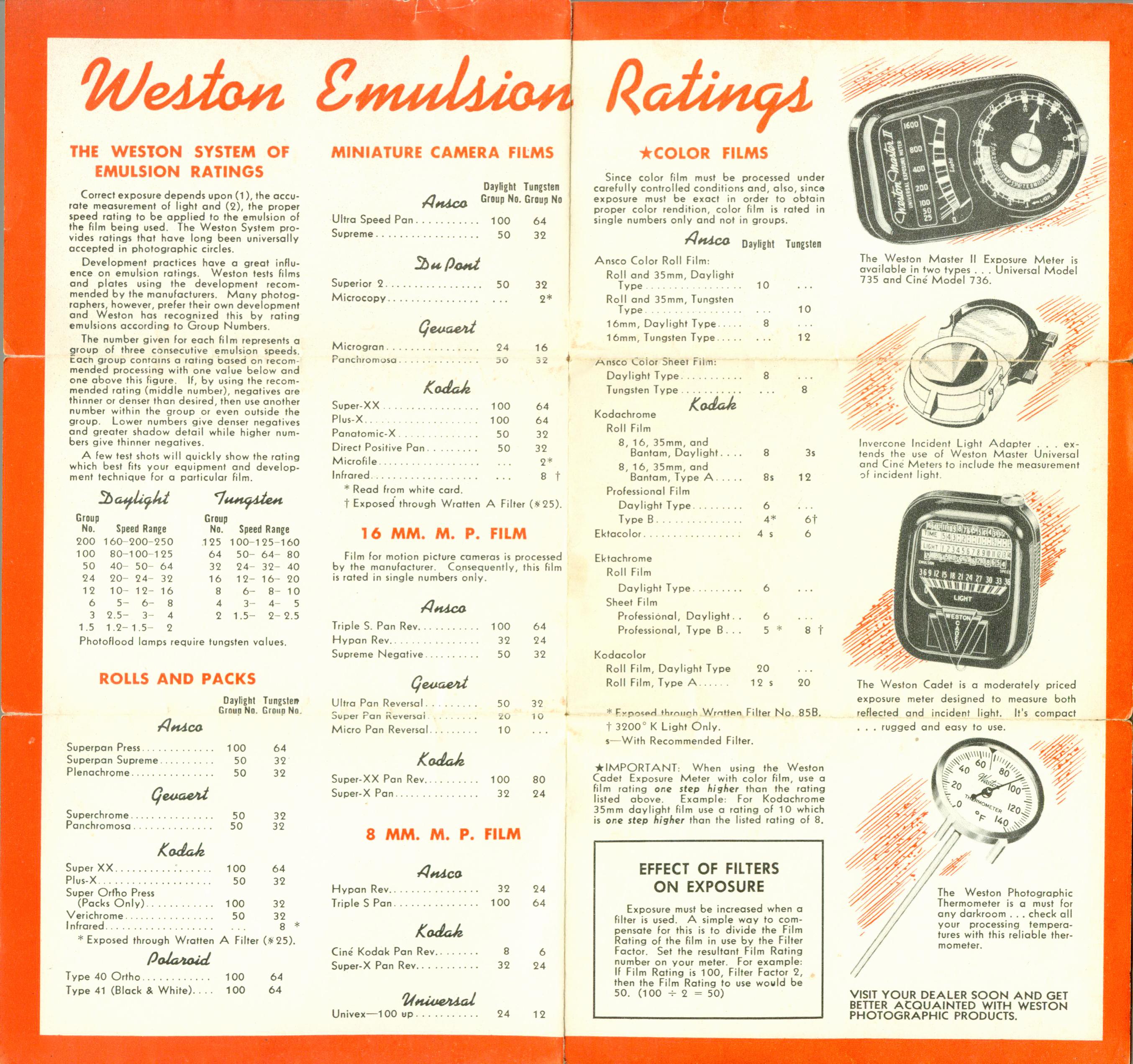
Weston Master IIMany of my old classic cameras lack a built-in light meter. When I shoot film in these cameras I use a meter that was in wide use back when these cameras were made. That meter is the old standby Weston Master II. This meter uses a seleium cell and has two ranges. The door on the back pops open for low light and is closed in bright light. All in all the meter works very well. The readings it gives are consistent with the meter on my Nikon FE2. Best of all, this meter only cost me $10. Using the meter is very simple. To start, you have to set the emulsion speed. Press the button at the bottom of the meter and then push the little tab that sticks out from underneath the main dial until the speed setting you want is visible in the little window. If you can’t see the window, turn the main dial until you see it.
To get a light reading, hold the meter in front of you parallel to the ground and read the number the needle points to. Rotate the main dial until the arrow on the dial points at the number and then read the shutter and aperture settings from the dial. That’s it. As with any light meter, remember that the reflectivity of the surface you are reading will affect the readings. On any meter, light colored surfaces will tend to give a setting that produces underexposure. One thing you have to adjust to when using these old meters is the changes in film emulsion ratings over the years. Emulsion ratings were not standard at the time the meter was made and most meter manufacturers came up with their own system and then published charts for the popular films. I have uploaded a 300dpi scan of the chart Weston published for this meter. The changes in emulsion ratings presents a problem if you want to use one of these meters. You need to know what the settings are for modern ASA/ISO speed ratings. The following image is a scan of a chart I found in the back of a Minolta A camera manual. It shows equivalent values for Weston, ASA and DIN. Note, however, that the equivalent for ASA 100 is DIN 22 on this chart. Today, ASA 100 is DIN 21.
Unfortunately, I dropped the meter one day and the needle jammed. I either had to start using it as a paper weight and get another meter, or try to fix it. As it turned out, the fix to the meter was very simple. The impact had dislodged the coil from its bearings and slightly bent the springs on the needle. All I had to do was pop the coil back in place and then gently bend the spring so that the needle return position was back at zero. The Weston Master III is supposedly nearly the same as the model II. According to Romney’s text, the III has a piece of foil on the back that covers the screws instead of the screwed on plate. You have to poke holes in the foil back to get to the screws.
|
 I’ve found that a setting of 64 on my meter produces good results with TMax 100 film. A setting of 80 works also, but seems to produce slight underexposeure. The best thing to do is to just shoot a roll of test shots using different settings and then use the setting that gives the best negative.
 |
Start by removing the two screws that hold the name plate on the back. Lift of the plate.
The large screw in the center is an adjustment screw and doesn’t come out. |
 |
With the nameplate out of the way, you can see the two screws holding the back in place. Unfortunately, these screws have some type of “star” head on them. I didn’t have a tool to fit them, so I pushed against the edge with a small screwdriver until I got the screws started. Then, I used tweezers to remove the screws. Before reinstalling the screws I used a screw slot file to make a slot in the head.
With the screws removed, slide a knife blade along the bottom of the back cover and lift it up. Note that the chrome strip is attached to the back cover. You need to lift from the bottom then tilt the back up slightly. There are two studs at the top that hold the back cover in place. |
 |
With the back off, you can see the meter movement. The two brass screws hold the front cover in place. Remove these two screws. |
 |
There is a third screw at the top that needs to be removed
Also remove the door over the light cell. You can see here the two studs that fit into holes in the top cover. These studs can fall out, so watch for them. |
 |
With the screws removed, the front cover will lift off. There is a spring at the bottom underneath the cover that pushes against the release button on the bottom. This button has to be pressed to change the film speed setting. Be careful that the spring doesn’t fall down into the meter.
With the front cover off you can see the problem clearly. The coil should be centered on the magnet but is sitting off-center. I gently put the spindle back in the bearings and the needle begain to swing freely again. However, the needle wouldn’t return to it’s zero position. After a little head-scratching, I realized that the coiled springs in between the coil and magnet had been slightly distorted. Pushing these gently back a bit solved the problem. This is as far as I needed to go in fixing the meter. It looks as if you remove the two large screws on the front and the screw holding the copper connector and the entire meter will then lift out.
Source: http://pheugo.com/cameras/index.php?page=westonmtr
Manual free download: |
